
When an N3 Satellite is configured as DMX slave, it enables external DMX to control the Ketra lighting system. The N3 receives data from a DMX driver, then patches (transmits) that data to Ketra groups (i.e., to each control zone’s lights).
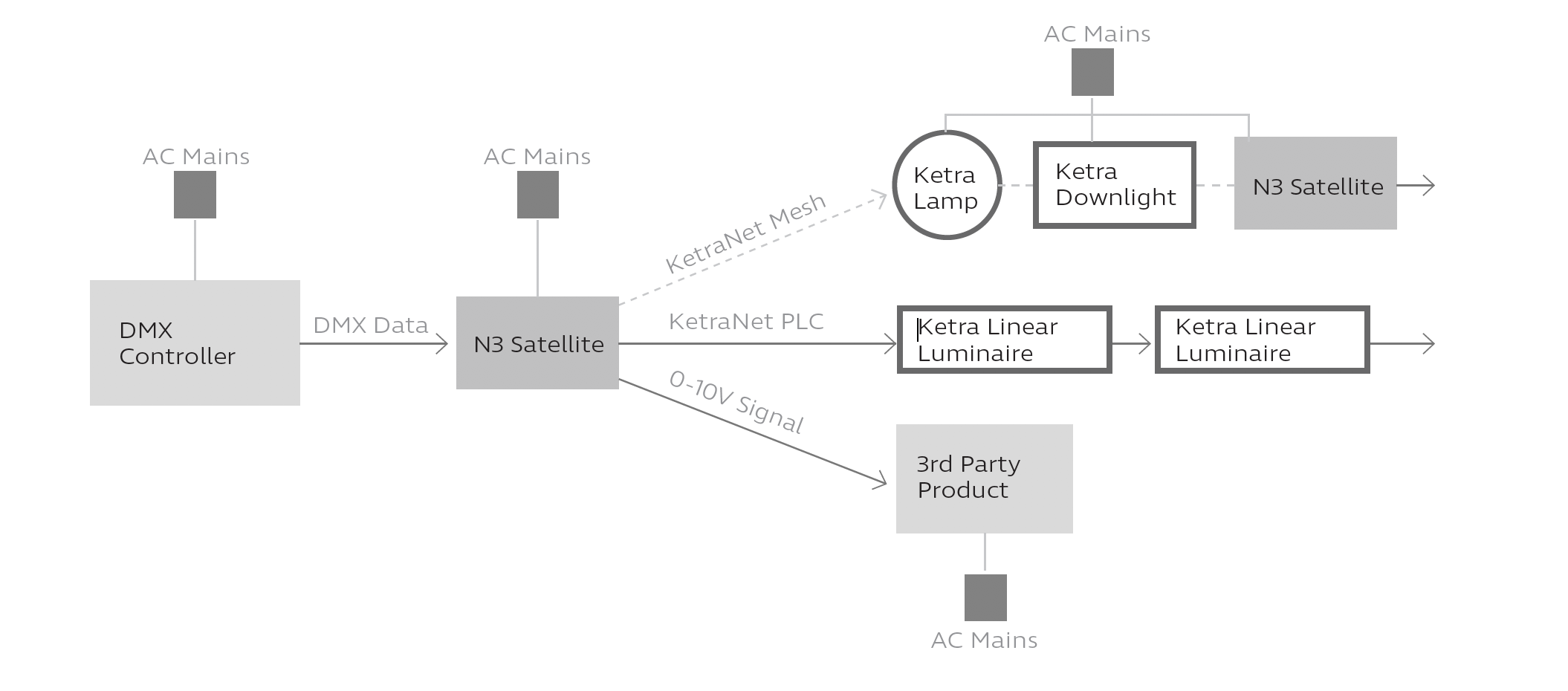
The N3 uses any combination of 3 methods to patch DMX data to Ketra groups:
- KetraNet Mesh — wireless communication between the N3 and Ketra products, including lamps, downlights, and other N3 Satellites
- KetraNet PLC — wired communication between the N3 and an attached run of linear fixtures
- 0-10V signal — wired communication between the N3 and a third party product that accepts 0-10V intensity information
Workflow
1. Physically install and connect power to Ketra’s products.
2. Run the Design Studio software and create an installation file.
3. Create groups and add devices as required for project application.
4. Set up DMX profiles in Design Studio and select which lighting groups each profile is mapped to. "Publish” Ketra installation data.
5. Set up 3rd party controller to send the corresponding DMX profile ranges to the Ketra N3 Satellite.
For instructions on steps 2-5, see the Design Studio user manual.
Performance
The N3 patches DMX to Ketra devices in 55-channel data frames, one frame at a time. Once all frames have been sent out, a final “go” command is issued and all of the affected lighting products change state in unison.
The frame rate varies based on whether data is being patched over wire or KetraNet Mesh.
- Over wire, the N3 patches data at a rate of 20 Hz, or ~20 f/s. So, patching a full DMX universe would take at most ~0.5 seconds. That means speed is seldom an issue when patching solely by wire.
- Over KetraNet Mesh, the N3 patches data at a rate of 0.67 Hz, or ~0.67 f/s (1.5 seconds per frame after the first frame). So, patching a full DMX universe would take up to ~13.5 seconds.
Note: In an application where both KetraNet Mesh and wired communication (KetraNet PLC or 0-10V output) are used, the wired communication speed will “downgrade” to match the KetraNet Mesh speed. This ensures that all devices change in sync.
Since the delay when communicating over KetraNet Mesh can be significant, we recommend reading Wireless Latency (below) to calculate and account for delays.
Performing Fades
Fade rates should be sent from the DMX controller as a parameter.
Ketra offers profiles that include a fade rate parameter (e.g., RGBIF). When the N3 Satellite receives the DMX input, it will relay the fade value to Ketra groups; when the “go” command is given, the groups will transition to the desired color and intensity over the period of time set by the fade rate parameter.
This is especially important in applications that patch DMX input over KetraNet Mesh. Due to wireless latency, initiating a fade up or fade down from a DMX console may result in the wireless Ketra lights making large steps in intensity rather than smoothly transitioning. Sending fade rate as a parameter eliminates this problem.
Wireless Latency
If the N3 Satellite has to patch DMX data to at least 1 KetraNet Mesh device (lamp, downlight, or other N3 Satellite), you may experience delays between the beginning of transmission and the Ketra lights’ response.
In most cases, the first 55-channel data frame broadcasts immediately. After the first frame, each additional frame requires up to 1.5 seconds to broadcast. Once all frames have been broadcast, a final “go” command is issued and all of the affected lighting products change state in unison.
Note: The 1.5-second delay occurs between all broadcasts. Therefore, the first 55-channel frame will only experience a delay if the N3 Satellite broadcast a frame from another command less than 1.5 seconds previously.
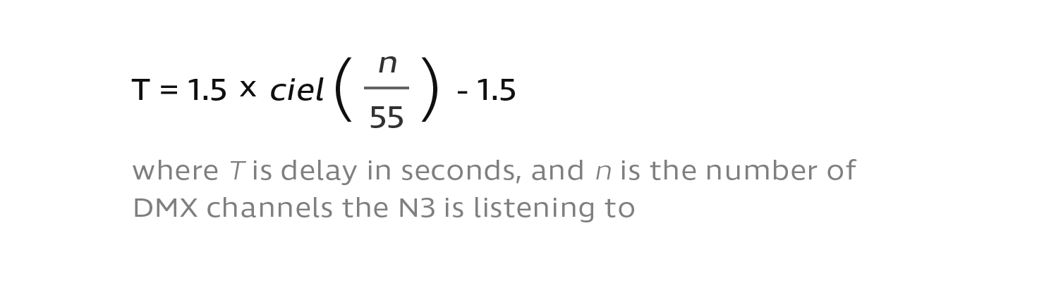
To calculate the maximum delay possible (in seconds), use the following four-step calculation:
1. Divide the number of DMX channels the N3 is listening to by 55. (You do not need to count the same channel range multiple times if you are patching it to multiple groups.)
2. Round up to nearest whole number.
3. Multiply the result by 1.5.
4. Subtract 1.5 to represent the first frame, assuming no other frame was broadcast within 1.5 seconds previously.
Note: 1.5 seconds is a maximum figure. Actual latency time varies with signal interference.
Example: An N3 patches 60 DMX channels over KetraNet Mesh. 2 data frames will be required: 1 for the first 55 channels, and 1 for the remaining 5 channels. The first frame experiences no delay, while the second takes up to 1.5 seconds to broadcast. Therefore, the maximum latency is 1.5 seconds.
One way to account for wireless delays is to calculate the expected latency using the formula above, then send the DMX values that far in advance of when a transition should occur. Most DMX controllers include timeline editing and can support this use case.
However, since 1.5 seconds per frame is a maximum figure, the transition may occur before the desired time. How much before depends on the number of data frames being broadcast. This is one reason we recommend against using Ketra’s wireless network for live applications such as theatre.
Wireless Restrictions
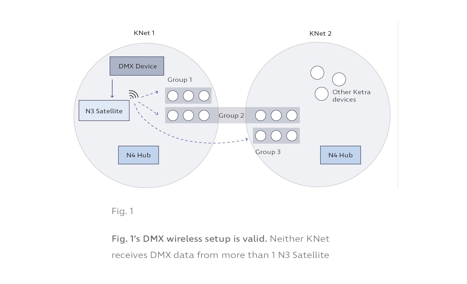
Only 1 N3 Satellite can wirelessly patch input per KNet. A KNet refers to all the devices associated with a single N4 Hub.
- If the installation only has 1 N4 Hub, then only 1 N3 Satellite can wirelessly relay DMX commands.
- If the installation has multiple N4 Hubs, each KNet can only receive wirelessly-patched DMX data from one N3.
Fig. 1 illustrates a valid DMX setup in an installation with multiple N4 Hubs. An N3 Satellite in KNet 1 wirelessly relays DMX commands to groups in both KNet 1 and KNet 2. Fig. 2 shows the same setup slightly altered to be invalid.
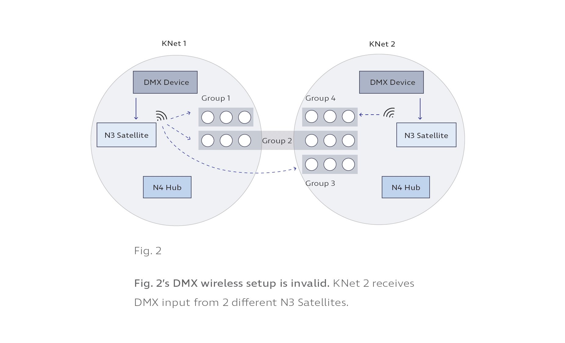
Any groups that violate this rule will not appear in Design Studio as available groups for patching DMX data to.