Some configurations in Design Studio are required before a DMX source can begin controlling the Ketra system. DMX sources interface with the Ketra system via the N3 Satellite. The N3 can take a full universe of DMX-512A, and Ketra provides a high number of profiles to account for a variety of situations.
Before making any configurations, make sure you know what parameters the DMX source is outputting and also what channels it will be using to talk to the Ketra system.
The N3 Satellite will listen to whichever channels you specify in Design Studio, then convert the input data to color and intensity configurations to propagate (“patch”) to Ketra groups. You can set up multiple profiles and map their configurations to as many groups as needed.
Example:
Important Notes:
- If any of the groups to which the N3 will patch DMX contain wireless devices (Ketra lamps, downlights, or other N3 Satellites), you will experience time delays and you may also encounter restrictions on which groups you can patch. These are covered in Wireless Patching Limitations, below.
- If you intend to use the DMX source to fade Ketra lights, set the source’s fade time to 0. Fade needs to be configured as a parameter taking up a channel, such that the N3 (rather than the DMX controller) can execute the fade.
If the N3 Satellite will only be patching DMX to directly-attached luminaires or onboard analog outputs, skip to Enabling DMX Input.
Wireless Patching Limitations
If the N3 Satellite will be relaying DMX input wirelessly (even if it will also be relaying DMX commands by wire), all of the following limitations apply.
Wireless broadcasting incurs a time delay. The N3 relays DMX input over KetraNet Mesh in 55-channel data frames, one frame at a time. In most cases, the first frame broadcasts immediately. After the first frame, each additional frame requires up to 1.5 seconds to broadcast. Once all frames have been broadcast, a final “go” command is issued and all of the affected lighting products change state in unison.
Note: The 1.5-second delay occurs between all broadcasts. Therefore, the first 55-channel frame will only experience a delay if the N3 Satellite broadcast a frame from another command less than 1.5 seconds previously.
To calculate the maximum delay possible (in seconds), use the following four-step calculation:
1. Divide the number of DMX channels the N3 is listening to by 55.
2. Round up to nearest whole number.
3. Multiply the result by 1.5.
4. Subtract 1.5 to represent the first frame, assuming no other frame was broadcast within 1.5 seconds previously.

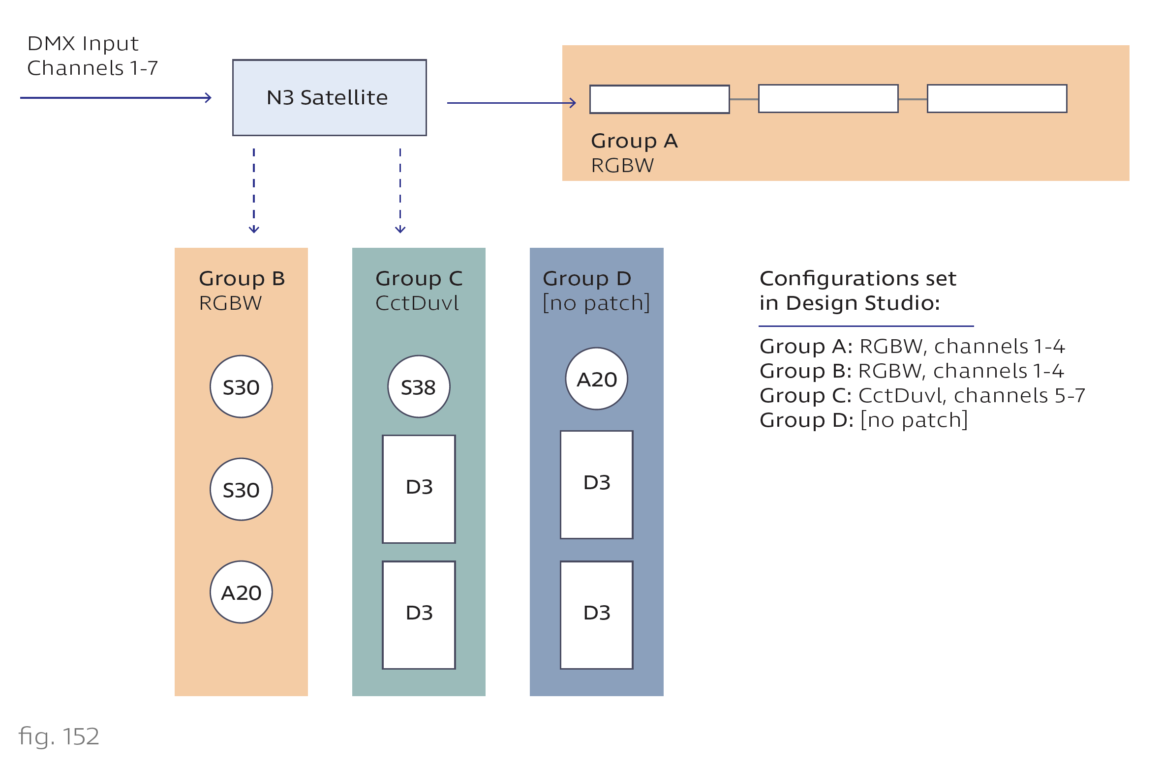
Example: In the diagram pictured in fig. 152, an N3 patches channels 1-4 (RGBW) to Groups A and B, and it patches channels 5-7 (CctDuvI) to Group C. The number of channels to which the N3 is listening is 7. Since 1.5 x ceil (7/55) - 1.5 = 0, there will be no detectable delay between the start of transmission and the time when the lights change color.
Note: If the N3 patches DMX input by wire and KetraNet Mesh, the wired communication speed will downgrade to match the KetraNet Mesh speed. This ensures that all devices change in sync.
Fade rates must be sent as a parameter. Due to the wireless latency discussed above, initiating a fade up or fade down from a DMX console may result in the wireless Ketra lights making large steps in intensity rather than smoothly transitioning.
To ensure a smooth transition, Ketra offers profiles that include a fade rate parameter (e.g., RGBIF). When the N3 Satellite receives the DMX input, it will relay the fade value to Ketra groups; when the “go” command is given, the groups will transition to the desired color and intensity over the period of time set by the fade rate parameter.
This enables you to calculate the expected wireless latency using the formula in fig. 153, then send the DMX values that far in advance of when a transition should occur. Most DMX controllers include timeline editing and can support this use case.
Example: A DMX512 theatrical console outputs 60 bytes of data on 60 channels, including several that control fade rates for various groups. The N3 will broadcast the input over KetraNet Mesh with a wireless latency of 2.7 seconds. You can set a trigger on the theatrical console to output information to the Ketra system 2.7 seconds before the desired transition. All Ketra lights will change in unison at the expected time.
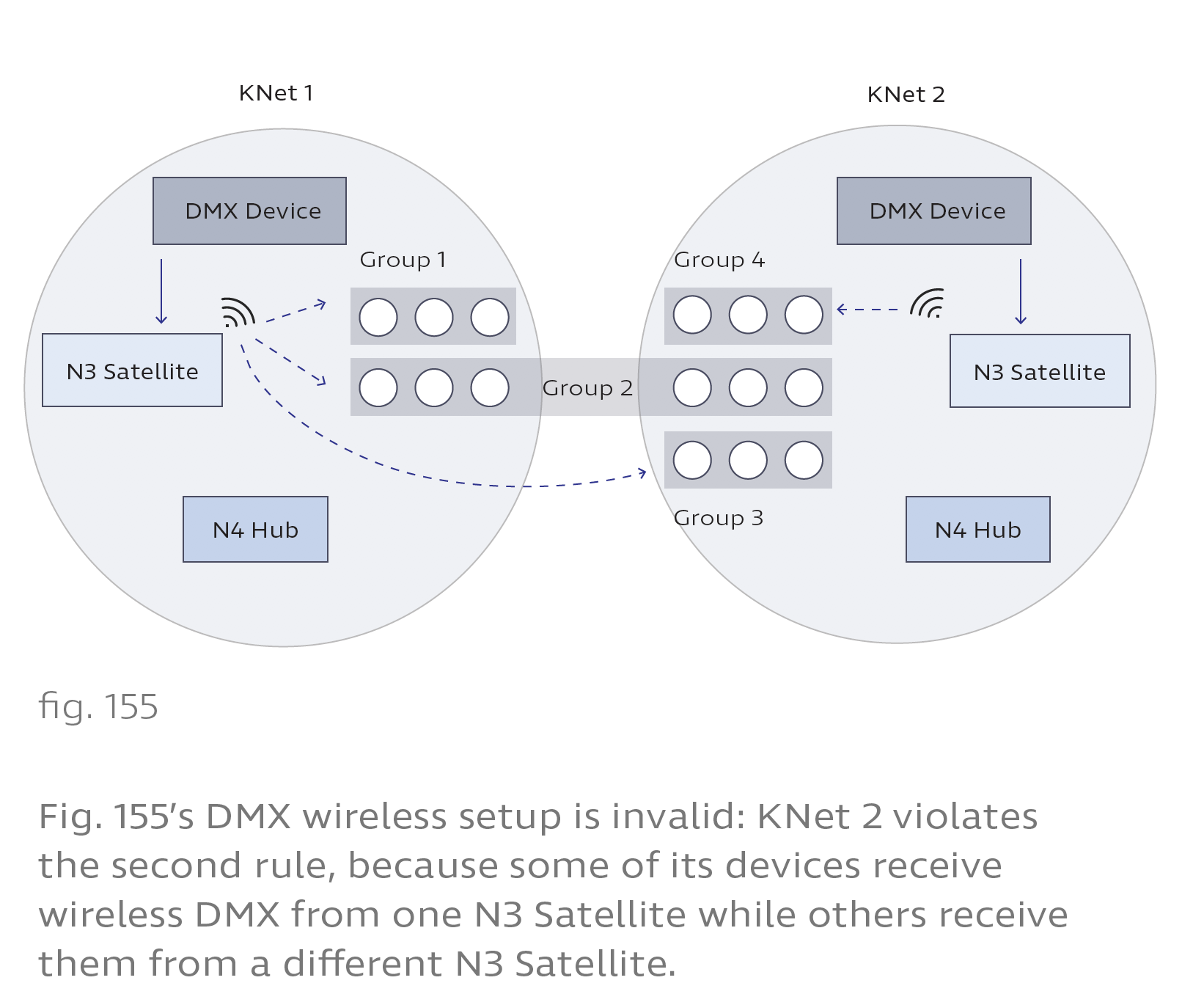
Only 1 N3 Satellite can wirelessly patch input per KNet. There are restrictions on the number of N3 Satellites that can patch DMX input wirelessly to unattached groups or other N3s.
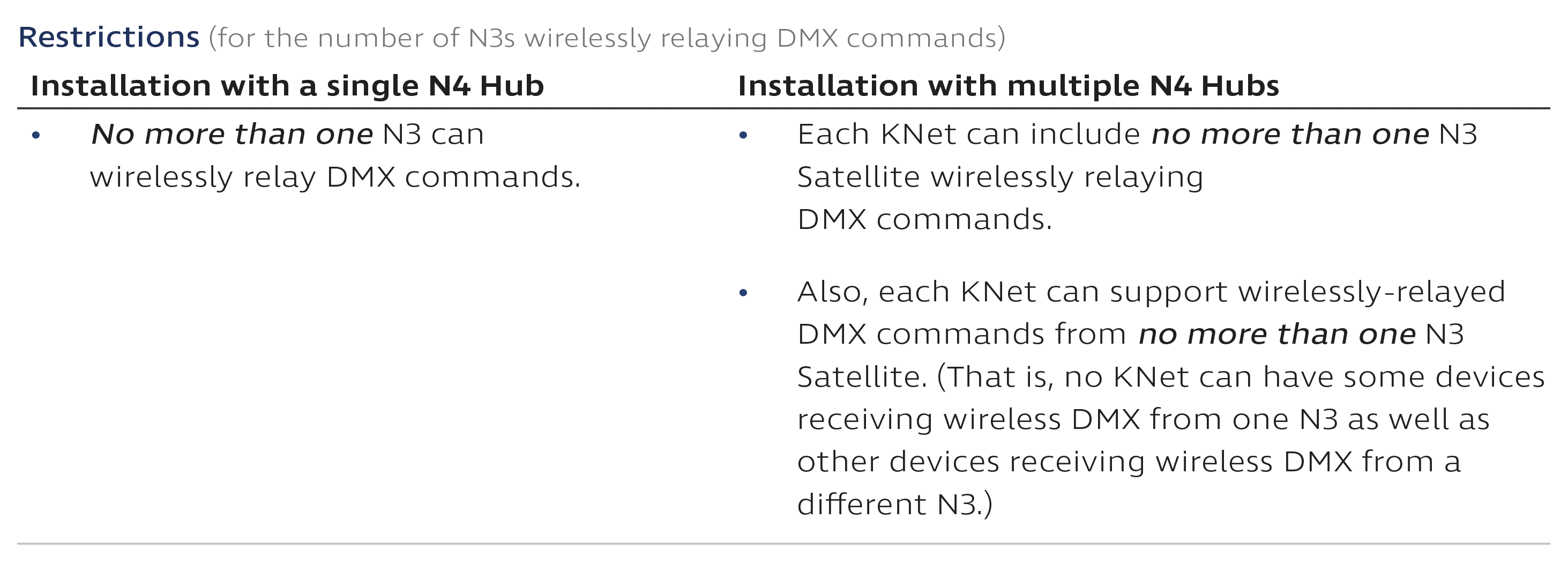
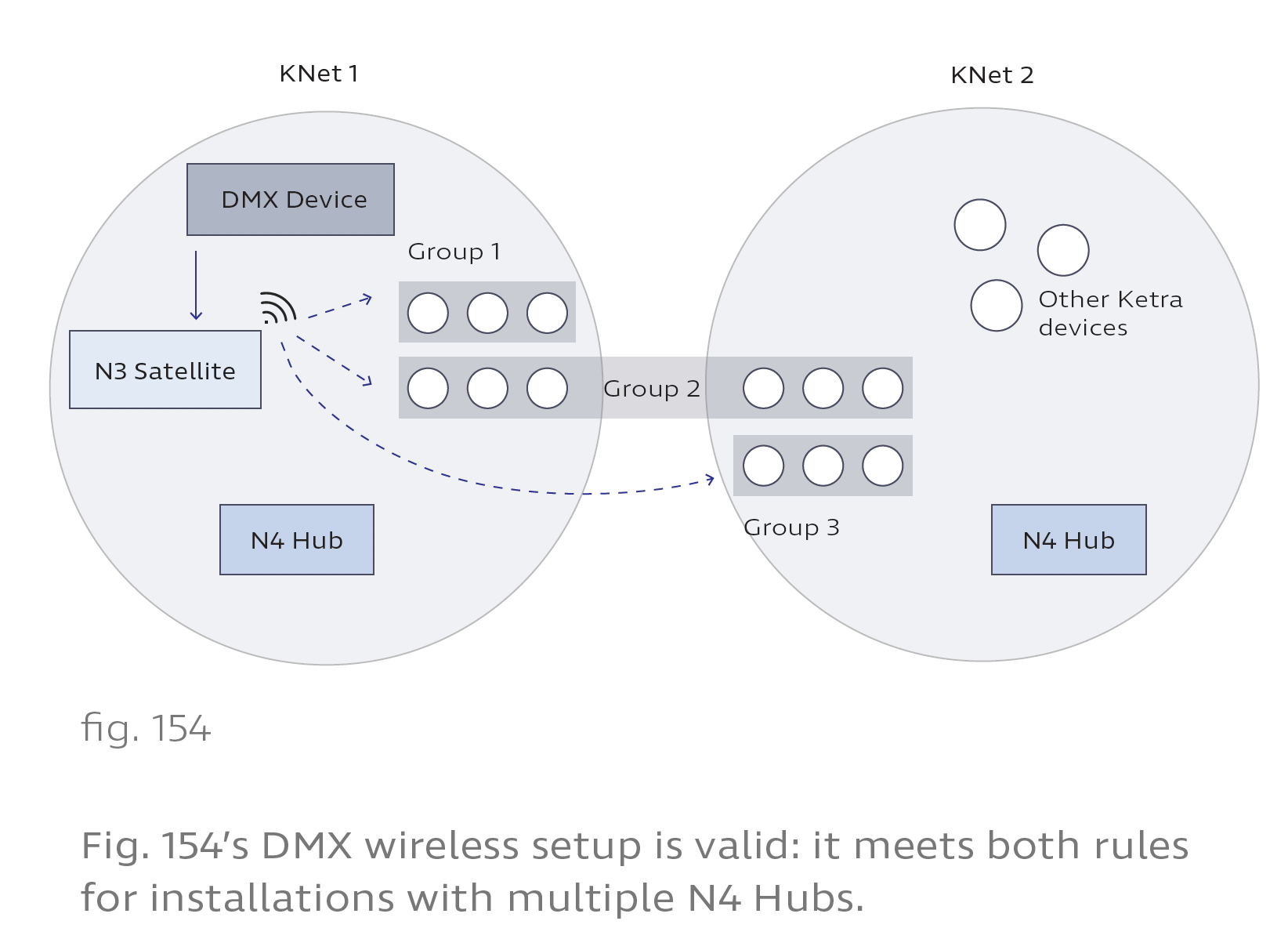
Fig. 154 illustrates a valid DMX setup in an installation with multiple N4 Hubs. An N3 Satellite in KNet 1 wirelessly relays DMX commands to groups in both KNet 1 and KNet 2. Fig. 155 shows the same setup slightly altered to be invalid.
DMX Input Instructions
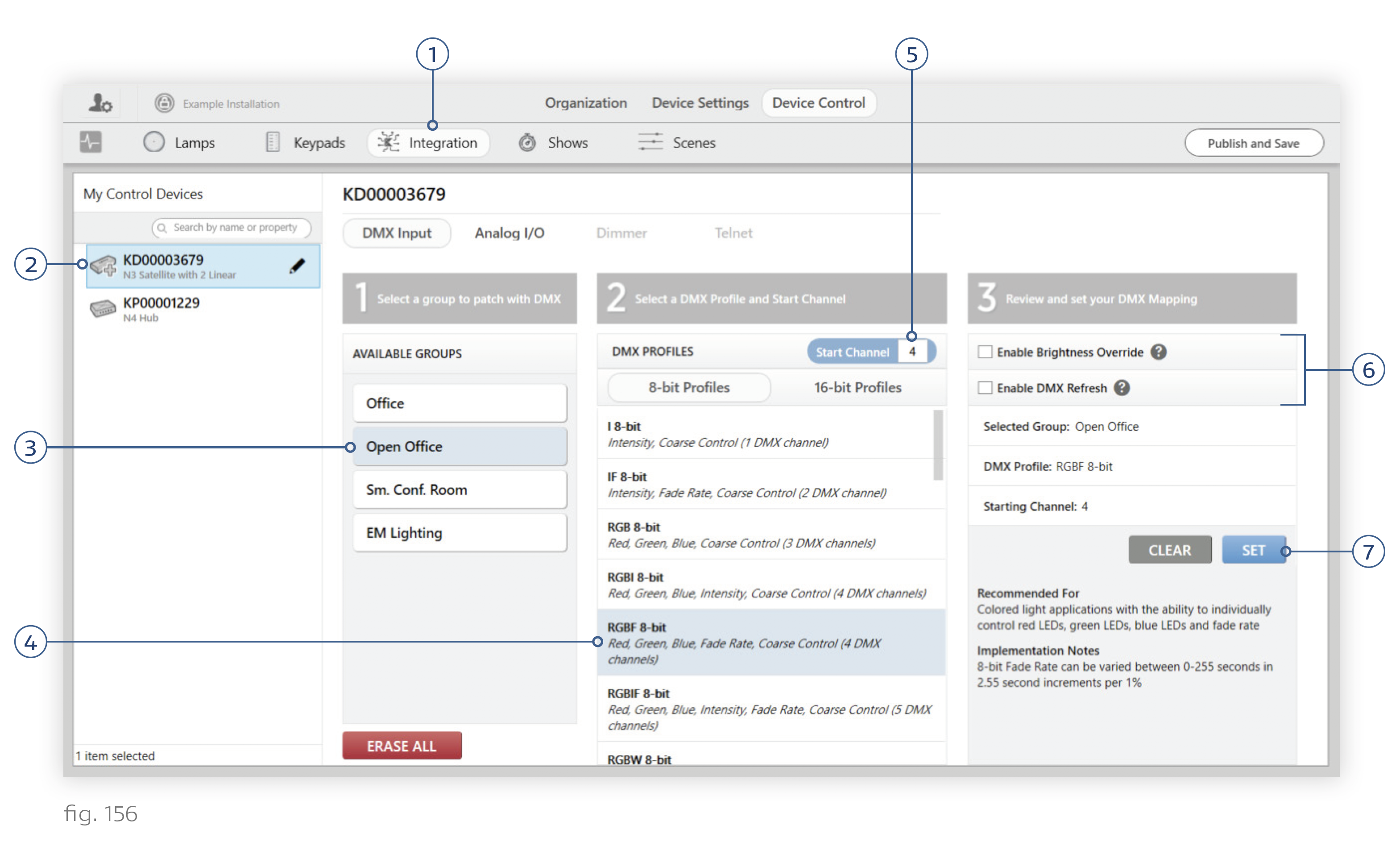
To configure an N3 Satellite to accept DMX input, follow these steps (see fig. 156):
1. Go to Device Control > Integration.
2. Select the N3 Satellite. At this step, satellites will not identify themselves by flashing indicator lights when selected.
3. Select a group to patch with DMX input. Design Studio removes groups from the Available Groups list if they violate the rule that each KNet can only receive wireless DMX patches from 1 N3 Satellite.
Notes: -- When patching additional groups, you will be able to reuse these input channels. However, avoid patching DMX to multiple groups that overlap, e.g., parent and child groups. -- Groups that contain analog outputs or dimmers, or whose subgroups contain analog outputs or dimmers, can only be controlled by intensity profiles.
4. Select a DMX profile for the group.
Note: To perform fades on wireless Ketra devices, pick a profile with the ‘F’ (Fade) parameter. The DMX source should be configured to output fade rates as a parameter rather than executing the fades itself. For more details, see Wireless Patching Limitations (above).
5. Set the profile’s starting channel. Based on the profile you chose, Design Studio will automatically determine the number of additional channels to listen to for input data.
Example: The DMX source outputs 8-bit red, blue, green, and white values on channels 14-17. In Design Studio, the profile and starting channel should be RGBW, channel 14.
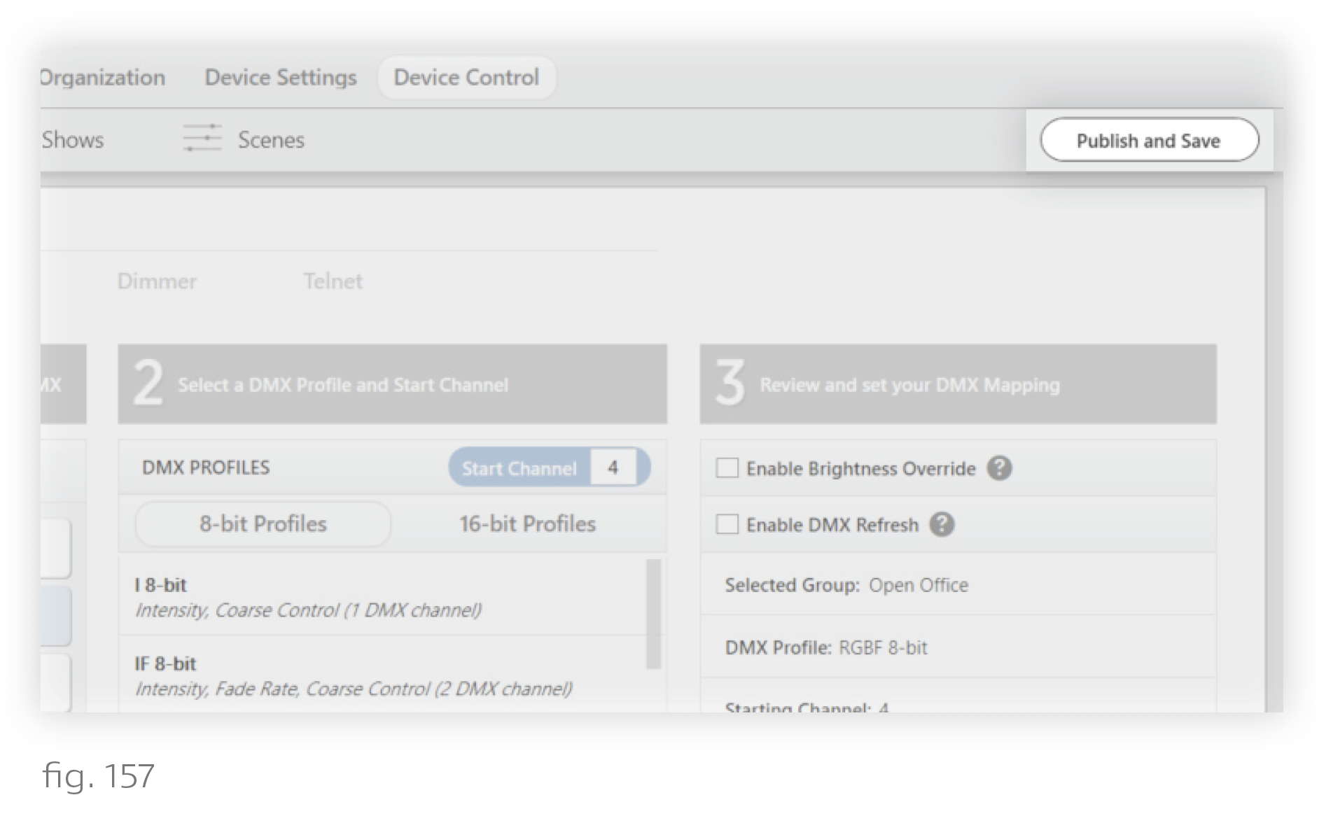
6. Optional: Set Brightness Override or DMX Refresh.
- Enable Brightness Override: This grants the DMX source full control of the group’s intensity. The source’s intensity commands will override those of any Ketra devices like keypads or shows.
- Enable DMX Refresh: This ensures that the group will return to its current DMX values within 10 seconds if changed from another control source. Do not use this if a keypad also controls the group. The primary use case for this feature is to enable you to test lighting content from Design Studio, knowing that the lights will revert back to their DMX values within 10 seconds.
7. Click Set. A checkmark should appear next to the group.
8. Repeat steps 3-7 for other groups as needed. You can reuse channels for separate profiles. For example, Group A might be patched an RGBI profile (red, green, blue, intensity) for channels 4-7, while Group B is patched an IF (intensity, fade) profile for channels 7-8. Both profiles use channel 7 for intensity.
This ability to overlap profiles can reduce wireless latency delay by lowering the number of channels the N3 has to broadcast. However, it can also cause problems if you accidentally overlap profiles that shouldn’t overlap. In the example above, Group B would behave unexpectedly if it were patched CctDuvI for channels 7-9. We recommend keeping track of the profiles you use and the channels they correspond to.
9. Click Publish and Save in the top-right corner. Your configurations will take effect as soon as you publish. However, if you’ve selected a profile with Fade Rate and the fade channel is set to a very long fade, you may not see the devices respond immediately.